I believe FM 1-28 2015 follows the same logic. Optional guidance was added for tornado-resistant design.

Ibc And Fm What S The Difference When It Comes To Wind Design
FM 1-28 is intended to provide designers with general guidance for highly protected FM Global-insured buildings.

. These exacting standards help you reduce the chance of property loss due to fire weather conditions and failure of electrical or mechanical equipment. The 115 factor is replaced by them requiring the use of a higher wind map. This infor- mation can be found in Appendix D and is provided for proper- ty loss prevention purposes only.
A tool that is fully equipped according to the rules of Europe and FM for wind load calculation. Included in these is the appropriate FM Global Research minimum roof system wind uplift rating. Metal roof panel suppliers will give you a FM design table for this say 1-105 requires a panel at 5.
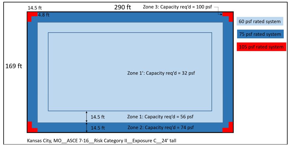
You enter the products and systems being used in the database you enter further values - such as the type of terrain the wind speeds on the site the height of the building and construction type - and thus. One key change relates to roof zone dimensions to align with the ASCE 7-16 Design Standards. Under FM 1-28 and also FM 1-31 Metal Roof Systems you need to use a roof panel that meets the FM loadings say 1-105 in the field for example.
The wind loads will vary in the corners perimeter and field of the roof. Instead FM 1-28 uses wind maps and basic wind speeds based on ASCE 7-05. FM uses their own wind speed maps.
FM 1-28 now uses pressure coefficients and zone dimensions based on ASCE 7-16 Minimum Design Loads and Associ-ated Criteria for Buildings and Other Structures How-ever FM 1-28 does not use ASCE 7-16s wind maps and basic wind speeds. This data sheet is intended to be used in conjunction with Data Sheet 1-28 Wind Loads to Roof Systems and Roof Deck Securement See FM Global Update Roofing Contractor February 2001. Signiicant changes include the following.
The first gives information on how to determine wind load. These and other factors are used in conjunction with FM Global Property Loss Prevention Data Sheet 1-28 titled Design Wind Loads to establish the uplift forces on the specific building. More on the specifics later FM Global is an insurance company and a purveyor of design and installation documents for roof systems eg Loss Prevention Data Sheets 1-28 Wind Design.
They incorporate nearly 200 years of property loss experience research and engineering results as well as input from consensus standards committees equipment manufacturers and others. All recommendations are for systems used within their Approval limits. Wd-1 fm lpds 1-28 provides a number of look-up charts and tables based on exposure wind speed and roof height which provide design wind loads for the field of the.
This Code Alert document summarizes changes made to the FM 1-28 Property Loss Prevention Data Sheet dated February 2020. Relating ASCESEI 7-10 Design Wind Loads to Fenestration Product Ratings is a technical bulletin jointly endorsed by AAMA Window and Door Manufacturers Association WDMA Fenestration Manufacturers Association FMA and the Door and Access Systems Manufacturers Association DASMAThe bulletin available free for download summarizes information about current. It goes from 85 - 184mph this is 3-second gust Please note most warranties end at 55mph even though they are designed to 90mph Roof height - it is more roof geometry for this one.
For wind design the IBC requires a roof system be designed based on ASCE 7 Minimum Design Loads for Buildings and Other Structures. Roof systems are only Factory Mutual Research-Approved for certain wind uplift ratings. FM LPDS 1-28 provides a number of look-up charts and tables based on exposure wind speed and roof height which provide design wind loads for the field of the roof.
In some cases depending on the roof dimensions building height and roof slopes four zones. The wind loads will vary in the corners perimeter and field of the roof. They use an 06 factor to convert to service level loads and then require the same 20 factor of safety that they had in 12.
However these loads can diverge higher from ASCE 7 if the building is over 60 feet tall or partially enclosed. All of this info can be found in ASCE-7 american society of civil engineers Design Wind speed - 90mph is typical in the US. 26 FM Global updated its Property Loss Prevention Data Sheet 1-28 Wind Design to reflect changes in its wind load determination methodology.
These and other factors are used in conjunction with FM Global Property Loss Prevention Data Sheet 1-28 titled Design Wind Loads to establish the uplift forces on the specific building. Wind loads determined per Data Sheet 1-28 are generally approximately 10 greater than those determined by using ASCE 7. DATA SHEET 1-28 WIND DESIGN This document was revised and pub- lished in October 2015.
We use the Roof Calculator for this. A separate table includes multipliers to go from an enclosed building the base assumption to a partially enclosed building. FM Global Design Wind Loads are determined by using FM Global Property Loss Preventio n Data Sheets 1-28.
1-28 wind design 1-28r1-29r roof systems 1-29 roof deck securement and above-deck roof components 1-30 repair of wind-damaged roof systems 1-31 metal roof systems 1-32 existing. Also FM 1-28 and. Would require an FM Approved Class 1-60 system design and follow the requirements of data sheet 1-29 for corner and perimeter enhancements.
The wind loads will vary in the corners perimeter and field of the roof. Following is an overview of the roofing-specific changes. Two Property Loss Prevention Data Sheets 1-28 Design Wind Loads and 1-29 Roof Deck Securement and Above-Deck Roof Components provide guidance with respect to designing for wind loads.
1-28 titled Design Wind Loads to establish the uplift forces on the specific building.
Ceu Wind Design For Roof Systems And Asce 7 2021 06 01 Building Enclosure

Proposed M36 Patrol Vessel Aircraft Carrier Warship Royal Navy

Ceu Wind Design For Roof Systems And Asce 7 2021 06 01 Building Enclosure
2
Ibc And Fm What S The Difference When It Comes To Wind Design
2
2

Linear Loaded Short Ham Antennas For Hf Hf Radio Ham Radio Antennas
0 comments
Post a Comment